The construction of Masalani suspension bridge on road E873
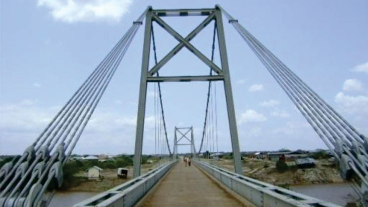
The construction of Masalani suspension bridge on road E873, across the Tana River, 30 km South of Hola town is now complete. The contract was awarded to Associated Construction Co (K) Ltd and supervision was carried out by the Chief Engineer (Roads) for the Ministry of Roads and Public Works.
The construction of Masalani suspension bridge on road E873, across the Tana River, 30 km South of Hola town is now complete. The contract was awarded to Associated Construction Co (K) Ltd and supervision was carried out by the Chief Engineer (Roads) for the Ministry of Roads and Public Works.
The bridge spans 134m with outer spans of 17m and 25m and a central span of 92m. The carriage way width is 3.7m.
Messrs Associated Construction Co (K) Ltd. carried out detailed designs to establish missing bridge details that were originally not provided as most parts were to be reused from the old bridge parts.
The design formed the basis of developing fabrication drawings for the steel components. Samples of cast parts were obtained from the existing components and physical and chemical tests analyzed in laboratory to compare their materials specification with the design analysis carried out. Fabrication of the steel components was carried out by Yerevan Steel Ltd. of Dubai who fabricated the girders, deck troughing, cross beams and bracings, towers and bearings. They also organized for the manufacture of the steel cast saddles and bearing pins. The cable system was supplied by Bridon International Ltd. of the UK who manufactured the main cables strands and anchors blocks. The erection of the steel girders, the deck towers and cable was carried out by Associated Construction Co (K) Ltd. using their local resources.
As this is a self anchoring suspension bridge, temporary support trestles were first provided by driving 300mm and steel pipe piles at designated location. Trestle extensions were then provided to the soffit level of the lifting jacks assembly. The bridge deck beams were conveyed into position by use of a 40 ton capacity pontoon barge with trestle and placed on a jacking frame assembly on the temporary supports. The towers were lifted in the assembled form by a crane and positioned on the piers and held in place by temporary stay beams. The towers were set to the designed initial pull back inclination. The first cable was set to the free cable geometry, ensuring the pre-set saddle marks on the cable corresponded with the saddle centre mark and the design level of the cable at the center is achieved.